


This insight focuses on the signal path from antenna to receiver. This path can go from a simple setup with just one antenna, cable and receiver to a complex multi amplifier installation. It is of course far beyond the scope of this document to get into the details and complexity of RF design. We tried however to write an insight that brings the basic RF signal path knowledge to the GNSS system users that would like to understand how the system is working or how to improve it. You don’t need to be an RF wizard to understand your GNSS signal path. There are a few basic things you will need to know to get you on your way. First we will have a look at the dB. This unit of measurement is used in almost everything related to RF so its something you really need to have a basic understanding of. We will then go over the different parts that make up your signal chain. To finish we will bring all these parts together to build a total signal chain and apply this knowledge on a practical use case.
Whenever you encounter RF technology, you most likely will be hearing dB a lot. Let’s get started with the WHAT question.
WHAT is a dB? As you probably know, dB stands for decibel. It’s a logarithmic unit that provides a convenient way of referring to ratios, such as the ratio between the amplitudes of an input signal and an output signal. It is a relative unit, so it compares for example two signal strengths. When you mention the gain of an amplifier is 30dB, it is a comparison between the input and the output of the amplifier. For a comparison in power, that is good for this use case the formula to calculate it is: 10log(Pout/Pin).
Here is a table with some practical values
| dB | power ratio |
|---|---|
| -30 | 0.001 |
| -20 | 0.01 |
| -10 | 0.1 |
| 0 | 1 |
| 10 | 10 |
| 20 | 100 |
| 30 | 1000 |
WHY are we using the dB value so much ?
Well basically there are two major advantages when using the dB. First, everything in RF has to do with very big ratio’s. Having a gain of 10000 is not as practical as saying 40dB. The second even more important property is that when you calculate a signal path using dB, it all comes down to adding amplifications and subtracting attenuations that would otherwise result in big multiplications and divisions that would be hard to work with.
This is a list of the different building blocks that make up the signal chain from antenna to receiver :
AMPLIFIER :
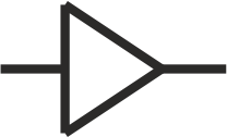 schematic symbol
As the name suggests an amplifier amplifies your signal. Simple enough right! Well it actually is simple up to the point where it gets hard… And then it really gets hard. The problem with amplifiers is understanding the little side effects that it brings with it. And the trouble is getting a feel for these effects without the need to become an RF wizard. Lets go over the main properties of an amplifier.
Gain: this is the easiest parameter to understand. Basically you want an amplifier to amplify your signals and the gain tells you how much your signal will be amplified. The only trouble might be that you are reading a value in dB that you are not familiar with. If need be reread the above chapter and try to get a handle on 10 -20 -30 dB. These are frequently used.
Noise figure: Here it gets complicated. We don’t want to go deep into this one, but some basic understanding can be a great advantage. First you need to understand that noise is all around us. Your antenna is not only picking up the GNSS signal, it is also picking up noise. It gets even scarier when you realize that every component you add to your system will also be generating noise. Even a simple resistor that is not even powered is generating… you guessed it NOISE. So it should be no surprise to you now that also your amplifier will be generating some noise. This is simply put what the noise figure expresses. A number signifying how much noise you are adding. The only problem here is that this is only true when your input noise levels are close to the standard 290K. Once you have amplified your signal, you will also have amplified your noise. When you give this new signal and noise combination to the next amplifier his noise figure will probably not even matter.
Non-linearity – compression point:
Aside from generating noise, an amplifier can also generate output signals that were not at the input from what is known as non-linearity or non-linear amplification. This non-linearity is perceived as signal distortion and produces harmonics and intermodulation products. The good news is that amplifiers today are extremely linear and if used correct you will probably never be faced with these problems. So key is using them in a correct manner. If you put input signals on the amplifier that are too high, the amplifier will start to exibit non-linear effects because you are overdriving the amplifier. Avoiding this is paramount for good signal integrity and by extension good GNSS positioning.
ANTENNA :
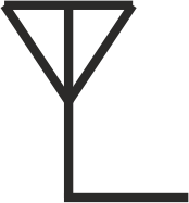 schematic symbol
The part you have in mind thinking about a high end system antenna is actually an antenna and amplifier build together in one casing to give you a highly integrated solution. The antenna itself is actually only the radiating element. The passive component that picks up the GNSS signal and outputs a verry small electric signal. These antenna’s can go from verry cheap chip antennas to high cost choke ring antennas with accurate determined phase centers. Not withholding that these expensive antennas can easily cost a thousand fold of a chip antenna, they basically do the same thing, converting an electromagnetic signal to a small electric signal. In all the high-end applications, this antenna will be integrated with an amplifier. This is done to give your total setup an as low as possible signal to noise ratio. If we would put a coaxial cable between the antenna and the amplifier, this would attenuate the noise and signal received by the antenna and thus making the noise figure of the amplifier have more effect on your signal to noise ratio. Remember that we mentioned that an amplifier has a noise figure that signifies how much noise is added by the amplifier. So it is best to put the first amplifier as close as possible to the antenna, effectively meaning it is integrated in most. For future reference, it is best to use the schematic symbol below that also clearly shows you that an amplifier is build in the antenna.
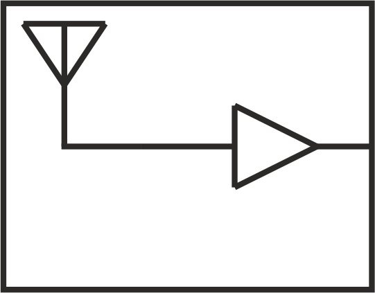 Schematic symbol with integrated amplifier
This active antenna, meaning it has a build in amplifier, again has many parameters. We will not go into detail on the possible antenna parameters, but for this insight and from a signal path point of view it is important to know the gain of the amplifier.
COAXIAL CABLE :
![]() schematic symbol
schematic symbol
The coaxial cable has two functions in the setup. The most import is of course the transportation of the GNSS signals from the antenna to the receiver. The second function is the transportation of power from the receiver to the amplifiers that are in your signal path.
A coaxial cable has many parameters, but in this insight we will only focus on attenuation. Attenuation is again a parameter that is expressed in dB and so expresses a ratio. It tells you the ratio of power you will receive out off the cable compared to what you put in on the other side. Simply put, the missing part is lost and therefore this is also referred to as cable loss. The attenuation of a cable depends greatly on frequency. To give you a typical overview of a much used cable, we have added the typical attenuation at a few frequencies of an Ecoflex-10 cable
| Frequency [MHz] | Attenuation [dB/100m] |
|---|---|
| 10 | 1.3 |
| 100 | 4.1 |
| 1000 | 14.0 |
| 1500 | 17.6 |
| 2000 | 20.6 |
As you can notice in the table above, the attenuation is expressed in dB/100m. So these are the numbers you can use when you have a cable of 100m. These numbers are easily adapted to other lengths, for example a 10m piece would present only a tenth of the attenuation. Another important effect to understand is that cable attenuation is very frequency dependent. A signal at for instance 1000MHz will have +- 6dB less attenuation then a 2000MHz signal through a 100m Ecoflex-10 cable.
So if you want to calculate your attenuation, you really need to know the frequency of your signals at interest. As you might know they are multiple frequencies and different satellite constellations making it a complex picture. From a signal path point of view, we need to consider frequencies from about 1000MHz to 1600MHz. We suggest going with the middle value of 1300MHz to not over complex the situation. For the Ecoflex-10 cable this gives about 16dB/100m.
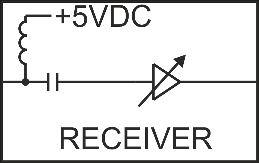
BIAS TEE :
 schematic symbol
A bias tee is a component that does not or should not do anything to your signalpath. Nevertheless it is important to know that it is there and to know what it does. As mentioned above, in most applications, the coaxial cable also acts as a conductor to transport power from the receiver to the amplifiers in the signal chain. So the amplifiers in your signal path, even the one that is integrated in the antenna draw power from the coaxial cable. It is the task of the bias tee to inject the power. Usually 5VDC is used as a voltage. Please note that sometimes higher voltages are used and not all amplifiers and antennas can handle these high voltages. The opposite might also be true. Some systems inject lower voltages then 5VDC that might not be enough for all amplifiers to guarantee correct operation. Good practice is to check the specifications before powering the setup.
Almost all GNSS receivers have a build in bias tee and provide power to the setup. When building large setups, it might be considered a safe choice to install a separate bias tee. This bias tee could then be installed just after the GNSS receiver or further in the chain.
RECEIVER :
 schematic symbol
The GNSS receiver is where we need to deliver the signal and thus the end of our chain. We will not go into all the different parts that make up a GNSS receiver, but it is important to understand the first few. As mentioned above almost every GNSS receiver has a BIAS TEE build inside. It is intended to power the active antenna or any amplifier that is installed on the line. After the BIAS TEE, there is an amplifier. This amplifier can be compared with the amplifiers on the line except that it is most likely an AGC amplifier. AGC stands for automatic gain control. This AGC amplifier tries to keep its output power to a constant level to make the following GNSS receiver parts work in their optimal range. This makes the receiver perform well over a wide range of signal input power.
As any building block you will find that the same parameters apply here. Two important parameters are again gain and noise figure. The gain is now expressed as a range because it is an AGC amplifier. For example the Septentrio AsteRx-m2a has a range of 15-45dB. So this specific receiver can adjust its gain over a range of 30dB. Looking at the noise figure, it is important to understand that normally the noise figure of a GNSS receiver will be worse than that of an amplifier. For a good performing amplifier you will get a noise figure of about 2dB where a noise figure of about 10dB is no exception for a GNSS receiver. Knowing this, it is important to get enough power into the GNSS receiver to not affect your signal to noise ratio’s. As with an amplifier overdriving the receiver will also have a negative effect on the performance of your receiver.

Lets now bring together what we have learned in a typical one amplifier setup. Lets presume you have an antenna with 30dB amplifier build inside. Your total cable attenuation is 35dB and you have purchased an amplifier that has a gain of 30dB. The big question that always rises is where to position your amplifier. There are some rules of thumb going around that usually work but now with the understanding you have lets reason about the setup and decide where to place it based on some numbers.
SIGNAL STRENGTH POINT OF VIEW
Basically your amplifier almost compensates your cable losses, so looking at it purely from a signal strength point of view it should not matter where you place your amplifier. As we have learned you can just add all the amplifications and cable losses to come to the end result here that the total path gives you +25dB from the antenna to the GNSS receiver and that is a good signal strength point for the receiver to work with.
SIGNAL TO NOISE RATIO
This part handles the noise figure of the amplifier. As explained, the amplifier will not only amplify the signal, but also the noise that is present on its input. And aside from amplifying the noise on the input, he will add some noise as well. The clue here is that as long as the noise level on the input is significantly higher then the noise that he is adding, there will be little to no effect to the signal to noise ratio. The question then rises, huw much is significant? We recommend using 10dB. You will understand that the higher you take this values the better for the signal to noise ratio, but then other problems rise.
We know that the amplifier has a gain of 30dB, so we know that the noise level has been amplified 30dB. If we want to keep it 10dB up, we must not add more then 20dB cable loss between the antenna and the amplifier. If we would put more cable between the antenna and the amplifier the signal to noise ratio will be affected more. If we put less cable between the antenna and the amplifier, the signal to noise ration will be affected less. But since we know that leaving 10dB sets us at a point where the signal to noise levels are almost unaffected this is a good place.
OVERDRIVING THE AMPLIFIER
As mentioned above, moving the amplifier closer to the antenna will give you a better signal to noise ratio. But as with all things in life, it comes with a cost. As you remember, an amplifier has a compression point, meaning that it will become increasingly non-linear if the signal power at its input rises. So placing the amplifier directly after the antenna is probably a bad idea because you put the full output power of the antenna onto the amplifier. Dont forget that we are talking about dB’s here and that 20dB cable loss in reallity means that only 1/100th of the power leaving the antenna actually reaches the amplifier!
There is also a big problem with estimating how much power the GNSS antenna will output. You know of course what the total signal strength of the received sattelites should be and you can estimate how much noise there will be present, but that is not all that is being received by the antenna. There can be many sources of signals that are being received by the antenna that you dont want, but are present. These signals could be filtered by the GNSS but if they have already distorted your GNSS signals by overdriving your amplifier the result will be that you have bad or no positioning. So since you dont know how much the total signal power will be, our advice is to take this parameter as save as can be. With other words, try to aim for the 10dB point as explained above and go with that cable distance.
With the 20dB attenuation you have from the cable, you can calculate the length of cable that should be between the antenna and the amplifier.
In this Insight we went over the different parts that make up the signal chain from a GNSS antenna to the actual receiver. We talked about the different aspects of the parts and how to understand them. Finally we applied this knowledge to an everyday signal chain and calculated what a good position for a GNSS amplifier would be.

