Stacking PPS pulse splitters
Exploration of the principles of connecting multiple pulse splitters, the signal integrity, propagation delays and how to optimize these factors.
Introduction
Pulse-per-second (PPS) signals are widely used in precise timing systems, such as those involving Global Navigation Satellite Systems (GNSS) and other synchronization applications. Ensuring good signal integrity provides the application with the needed accuracy and reliability of timing systems.
Our product range extends over multiple generations of 4 port and 10 port pulse splitters. It is also possible to connect multiple pulse splitters to achieve synchronisation to more than 10 consuming devices. But achieving high quality synchronisation needs insight in signal integrity, propagation delay and signal skew.
This article explores the principles of connecting multiple pulse splitters, the signal integrity, propagation delays and how to optimize these factors.
Connecting multiple pulse splitters
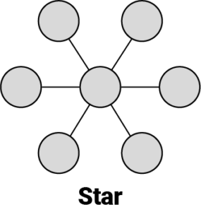
Star topology
A direct connection between the pulse driver and splitter is preferred to minimize signal delay. This connection method is straight forward as it connects each consuming device directly to an output of a splitter, resembling a star topology.
This connection method has the following properties.
- Driver loading: A clean termination is possible on all ports of the splitter. No additional loading is present on the driver.
- Signal Integrity: The PPS pulse is terminated in the in- and outputs of the splitter. The signal attenuation (signal loss) and reflections are minimized due to a single termination. A good signal quality is easily accomplished.
- Delay and skew: The propagation delay is at its lowest. Only the internal PPS splitter delay and coaxial cable delay are present. The skew between all consuming devices is the same as the skew of the splitter. These timing aspects are reduced to a minimum due to the internal function of the splitter products.
- Number of outputs: Only 10 consuming devices can be connected.
It’s clear that this star configuration has only one downside: only 10 consuming devices can be connected. When there is a need for more consuming devices, a synchronisation of multiple PPS splitters is needed. The following overview shows the properties of each connecting topology.
Linear topology
A sequential connection is created by connecting each device to the next one in line. This connection method is also known as the daisy chain. The first splitter receives the timing signal from the source, and each subsequent splitter passes the signal through an output to the next device in the chain.

- Driver loading: Only the first consuming device is connected to the source driver. The inputs of the subsequent splitters are directly connected to an output. This creates the possibility of a clean termination of all connections. A direct connection provides no additional loading on the driver.
- Signal Integrity: The PPS pulse is terminated in the inputs of the splitters. The signal attenuation (signal loss) and reflections are minimized due to a single termination. A good signal quality is easily accomplished.
- Delay and skew: An additional delay is created between the outputs of subsequential splitters, due to internal PPS splitter delay and coaxial cable delay. The skew of all outputs is increased by the delay of each added splitter. This delay is relatively constant over several factors including temperature, humidity and the manufacturing date of the PPS splitter.
- Number of outputs: Not all outputs of the splitters are available for consuming devices because one output is needed to drive the subsequent splitter.
Tree topology
This topology resembles a tree where each branch can connect to a consuming device or a subsequent splitter. The first splitter receives the timing signal from the source and passes the signal to a maximum of 10 branches.

- Driver loading: Only one splitter input is connected to the source driver. The inputs of the subsequent splitters are directly connected to an output. This creates the possibility of a clean termination of all connections. A direct connection provides no additional loading on the driver.
- Signal Integrity: The PPS pulse is terminated in the inputs of the splitters. The signal attenuation (signal loss) and reflections are minimized due to a single termination. A good signal quality is easily accomplished.
- Delay and skew: An additional delay is created when a splitter is connected to a branch. This is due to an internal splitter and coaxial delay between the connections. But the skew between all outputs is mainly limited to the difference between the consuming device nearest and furthest of the source.
- Number of outputs: All outputs of the splitters are available for consuming devices, except when a splitter is used to extend the tree.
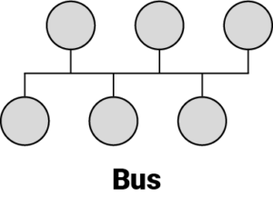
Bus topology
A bus topology or parallelization of the inputs can be used to supply the devices. All inputs are connected to the same signal.
- Driver loading: Each device connected to the source driver adds a load to the signal. It’s important to ensure that the total load does not exceed the driving capacity of the source. This involves determining the input impedance of each device to ensure the combined load is within acceptable limits.
- Signal Integrity: Maintaining signal integrity is critical. As the signal passes each splitter, there will be attenuation and reflections. Ensuring proper termination at each input minimizes reflections but will create additional load. An optimal balance can help maintain signal strength and accuracy.
- Delay and skew: The outputs of the subsequential splitters have a delay proportional to the cable delay to the previous input and the delay due to a lower slew rate. The skew of all outputs is quite similar to the skew of the outputs of a single splitter but the variation in skew is determined by many factors such as temperature, humidity, signal loading, drive strength, PPS splitter manufacturing date, etc. This creates a random skew between the different splitter outputs.
- Number of outputs: All outputs of the splitters are available for consuming devices.
PPS signal integrity
Signal integrity refers to the preservation of signal quality as it travels through a transmission interface. A PPS signal is a digital pulse that occurs once per second, typically used to synchronize timing systems. The signal’s characteristics, such as rise time, voltage levels, and impedance, can vary depending on the source and the components involved in its distribution.
A 50ohm coaxial cable is normally used for a PPS pulse signal. The 50ohm impedance standard is widely used in RF and high-speed digital systems due to its balance between power transfer and signal attenuation.
Key factors affecting signal integrity in a coaxial cable include:
- Impedance Matching: Proper impedance matching between the transmission line and connected components minimizes reflections and signal loss.
- Transmission Line Characteristics: The physical properties of the transmission line, such as length, material, geometry, and attenuation, influence signal propagation and quality.
- Noise and Interference: External noise and electromagnetic interference can degrade signal quality.
Strategies to Maintain Signal Integrity
To ensure signal integrity in 50ohm transmission lines, several strategies can be employed:
- Impedance Matching: Use impedance matching techniques, such as termination resistors and matching networks, to minimize reflections.
- High-Quality Materials: Select transmission lines made from high-quality materials with low dielectric loss and minimal resistive loss.
- Shielding and Grounding: Implement proper shielding and grounding techniques to reduce electromagnetic interference and crosstalk.
- Design Optimization: Optimize the physical layout and geometry of transmission lines to minimize signal degradation.
Factors Contributing to Propagation Delay
Propagation delay in PPS pulse splitters can be influenced by several factors:
- Pulse Shape and Distortion: The shape of the PPS signal can change as it propagates through the coaxial cable due to losses, interference and reflections. Termination will minimize the reflections but will increase the load on the driver. Typically, this results in a lower slew rate. Distortions in the pulse shape or the general signal integrity here of, can lead to inaccuracies in timing measurements.
- Pulse Splitter Response: The response characteristics of the pulse splitter used to detect and convert PPS signals, including their bandwidth and threshold voltage, can affect the propagation delay.
- Cable Length and Type: The length and type of cables used to transmit PPS signals can introduce delays.
Mitigating Propagation Delay
To minimize propagation delay in PPS pulse applications, several strategies can be employed:
- Optimizing Pulse Shape: Ensuring signal integrity by using common strategies can improve measurement accuracy.
- Using Short and High-Quality Cables: Utilizing short and high velocity factor coaxial cables between the driver and the consuming device will minimize the coaxial cable delay.
The pulse splitter response can not be further optimized on account of the internal operation.
Measurements on our 10 port PPS splitter
The factor of pulse distortion is visible when two measurements are compared. The first figure represents an unterminated input, and the second figure represents a terminated input. At the unterminated input we see an overshoot and oscillation at the edges of the PPS input pulse.


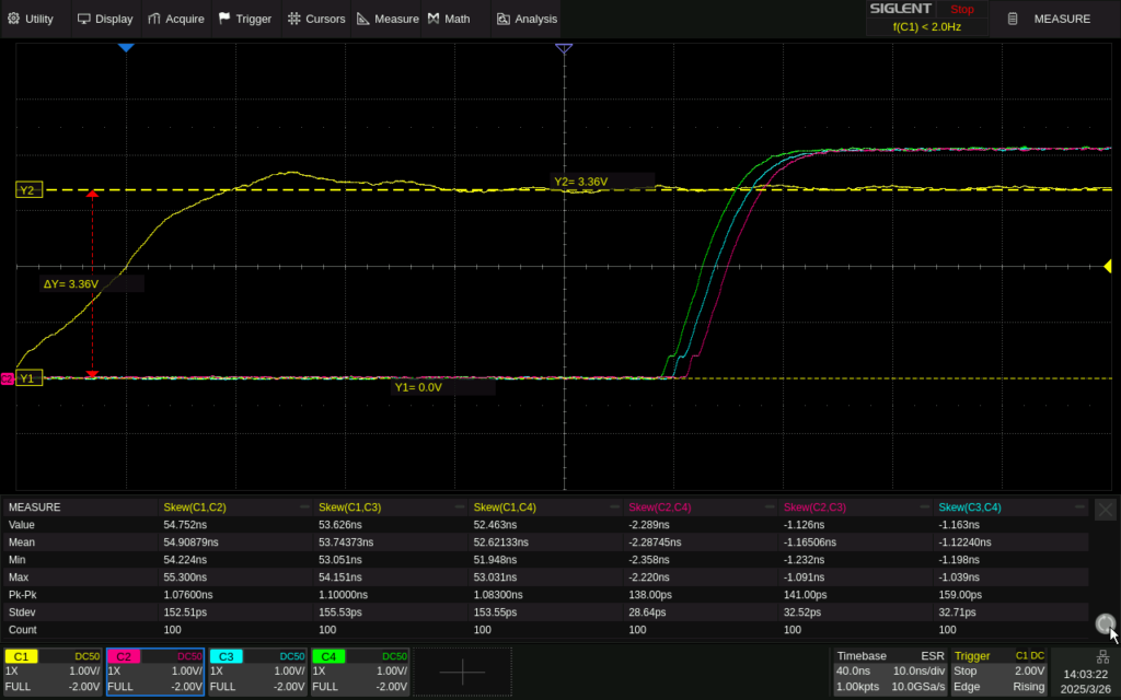
The image above shows a lower rising time and almost no overshoot on the terminated input signal. In addition, it shows a skew of less than 2.3ns between the different outputs.
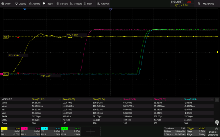
The oscilloscope image below shows us the measured propagation delay of two 10 port puls splitters connected in a linear topology. Channel 1, in yellow, is the input of the first splitter, splitter 1. We measure a delay of about 56ns between the input and the first output, on channel 2 in red, of the splitter. The second splitter input is connected to the tenth output of splitter 1. We see about the same propagation time between the first outputs of the two splitters, the difference between channel 2 in red and channel 3 in blue. Channel 4 in green shows the last output of splitter 2.
Conclusion
Our product range consists of 4 port and 10 port PPS splitters. If more than 4 consuming devices are needed in the application, it is best to upgrade to a 10 port splitter. The star configuration gives the best propagation delay and skew between all consuming devices. Only if more than 10 consuming devices are needed to be synchronized, a connection between splitters will be required.
Maintaining signal integrity in PPS signals is crucial for the accuracy and reliability of timing systems. Daisy chaining multiple splitters gives the advantage of a predictable and relative constant propagation delay. A good signal integrity is easy to accomplish because of the point-to-point connections. A great downside to this topology is the additional delay when more than two splitters are needed.
A tree topology has the same benefits of signal integrity as the linear topology. But 100 consuming devices can be connected to one source signal without adding more two times the internal splitter propagation delay. Because of the many advantages this topology is preferred.
If tighter skew of the outputs is needed, a bus topology design can be used. But the skew, and propagation delay, between the outputs is unpredictable due to manufacturing tolerances, temperature, humidity and input signal integrity. The input signal will be loaded with multiple pulse splitters which results in complex signal management due to signal loading and reflection. This topology is least recommended.
Our PPS splitters have an internal propagation time of about 50ns and a skew of the outputs of less than 2.3ns.

Interested in a tailored solution?
Connect with us
Through partnership, we deliver tailored engineering solutions—from land surveys to marine operations—designed to streamline processes, minimize risks, and maximize performance across industries