ABOUT THE PPS PULSE

What is a PPS pulse

PPS stands for “Pulse-per-second” and is an electrical signal used in time synchronization applications. The pulse is transmitted by a pulse generating device to one or multiple pulse consuming devices. The aim is to accurately synchronize the pulse consumers clocks to the pulse generator.

Depending on the application the purpose can be to get a relative synchronization between the consumers clocks to the generator or to get an absolute synchronization. With an absolute synchronization the receivers will also get time-date information send together with the pulse. The PPS pulse receiver will use the pulse as a mark when to synchronize its clock to the incoming time-date information.

PPS pulse generating devices can be Atomic clocks, frequency standards, GNSS receivers etc. On the consumer side there could be survey motion equipment, computers, telecom equipment etc.

A big problem regarding PPS pulses is that there is no dominating standard that can be used as reference. This has led to the point where every device manufacturer has its “own standard”. Here are some of the main parameters that can differ and influence the stability and reliability of your planned setup.

Signal type

Most PPS pulse generators will produce whats called a TTL level pulse. TTL stands for Transistor-transitor logic and is widely used on circuit boards to interconnect integrated circuits. It is however a not so ideal means to be used to interconnect different devices. We recommend using a TTL pulse only for a short distance. This is because it is a low voltage high impedance signal that is very susceptible to noise and will not give clean rising and falling flanks to reliable trigger on.

Within the TTL signal type there are different voltage standards. The most common used are either 3.3V or 5V TTL levels.

Some PPS pulse generators do not have a TTL interface, but use a 50 Ohm signal interface. The big advantage of these 50 Ohm pulses is that they match with the impedance of coaxial cables. This impedance matching is very important to allow for nice rising and falling edges. This in turn guarantees accurate triggering on the pulses.

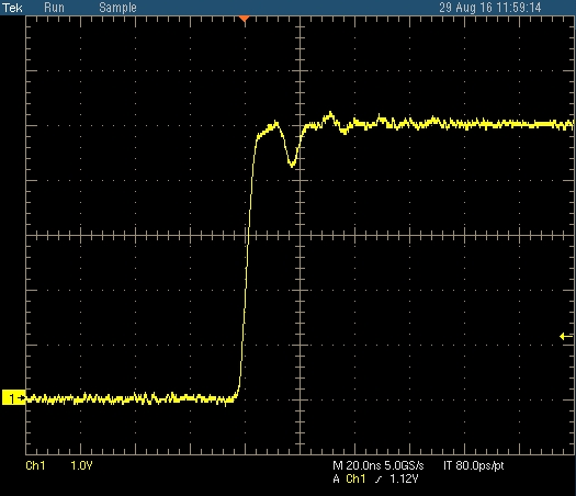
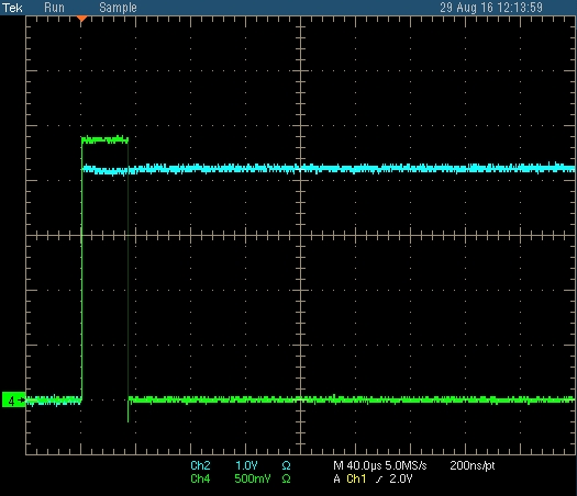
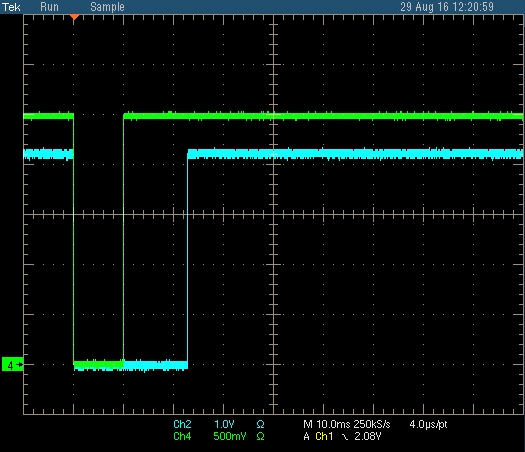
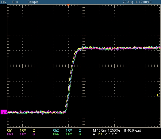
Below you will find two scope captures. The first is a TTL signal send over a 1 meter coaxial cable to a TTL receiver. You can see that it has a second unintended dip in the signal 20ns after the rising flank presenting a second rising flank. Depending on the cable used and the actual implementation of the PPS transmitter and receiver circuit, this setup can become unreliable. The second capture is from a 50 Ohm signal over a coaxial cable to a 50Ohm receiver. This will present a much better signal that can be send over longer coaxial cables while still give good results.

RS232 PPS signal 

For time synchronisation of a PC some applications still use the RS-232 serial port.  By toggling one control line, the PC is able to synchronise its clock to the incoming time message.  Since a PC does not have a real-time operating system synchronisation is sometimes hard on the short pulses. Making the RS232 line toggle sometimes gives better results because it is easier for the PC to trigger on. The capture on the right shows the resulting output. Please note that the voltage of the PPS pulse is +- 6V.

  • Green is the PPS input signal
  • Blue is the toggled RS232 PPS output signal

Most of our PPS splitters provide this toggled PPS output signal.

Signal length 

In the same manner as for the other parameters, there is no standard specification on how long a pulse should be. This is also a choice left to the individual device manufacturers . Depending on how the receivers triggering system works the pulse should have a certain length. One pitfall may be that the pulse is too short to trigger the pulse consumer input. Below are two captures of a GNSS receiver that generates a very short pulse of about 36µs.

  • The green line represents the GNSS output
  • The blue line represents our PPS splitter output

Rising flank or falling flank 

Most PPS pulses are meant to trigger on the rising flank of the pulse. This means that the PPS pulse generator will make the voltage rise from low level to high level to indicate the PPS mark. The line will stay high for a period of time and then drop to the low level again. The voltage drop has no special meaning but can be seen as a reset to accommodate the next pulse. As mentioned before this period can differ from device to device.

Less used but also possible are the falling flank pulses. Here the generator will make the voltage drop from high level to low level to indicate the PPS mark.

In the captures below you can see both possibilities. The green trace is the PPS input. Some of our splitter models are able to handle the falling edge trigger and will work for these signals. Signal conversion from falling to rising can also be accommodated.

How to distribute the PPS pulse

The first thing to understand before planning your installation is what type of pulse will be generated and what type of pulse do my different consumers expect.

The input of our  PPS pulse splitters can be configured to match the pulse generator output.

  • If the generator outputs a 50 Ohm pulse, set the 50 Ohm termination on the splitter input.
  • Select the trigger level of the input to match the signal level of the pulse.

If the generator does not have a 50 Ohm output it is recommend to keep the distance between the generator and the splitter to a minimal.

All the outputs of the PPS splitter will give you a low impedance 5V pulse. This can be connected to almost any pulse receiver. If you are using a long coaxial cable connection and the connect to a TTL imput, it will be best to provide an external 50 Ohm termination resistor on the input to match the signal impedance and avoid reflections on the cable.

Delays on the PPS signal

It is important to understand that everything connected between the PPS source and the PPS consumers will introduce delay. We will focus on two sources of delay in this article; coax cables and PPS splitters.

Coaxial cable delay

A PPS pulse will travel through a coax cable at a certain speed. The speed is very fast however it is not infinite. Thus it will introduce a certain delay. Depending on the coax cable length, this delay can become significant for some applications.

Fortunately you can calculate the delay accurately and check if this would present a problem for your application. To determine this delay you will need the velocity factor of the coax cable. Every coax cable should have this specified. This factor is the ratio of speed at which a waveform passes through the coax compared to the speed of light in vacuum. This factor differs from cable to cable and should be known for the coax that is being used. The speed of light is 299 792 458 meter/second but for this application the 300 000 km/second approximation will work fine.

CABLE TYPE VELOCITY FACTOR
RG-58/U 0.66
RG-213 FOAM 0.8
RG-223/U 0.66
ECOFLEX-10 0.86
ECOFLEX-15 0.86
AIRCELL 7 0.83

Since velocity factor signifies a factor relative to the light speed in vacuum, the higher the number the better with 1 being ideal. The best cables will give you a factor in the range between 0.8 to 0.9. Please note the differences in velocity factor between the different coax cables. The relative low quality RG-58/U that is often used for PPS signal distribution has a velocity factor of 0.66 compared to the high 0.86 velocity factors of the ECOFLEX cables makes a huge difference on longer cable lengths.

To determine the time the signal would travel we use the above velocity factor of ECOFLEX-15 and come to the following calculation

We verified the calculation in our labo with  a PPS pulse. We used one of our 4 port PPS pulse splitters to make the following measurement.

  • The yellow pulse in the generated PPS pulse at the input of the splitter.
  • The purple pulse is measured leaving the PPS splitter
  • The blue pulse is measured after the 100m ECOFLEX-15 cable

We measured a delay of 385.6ns. The difference of 2.2 ns between the calculation and the measurement is well within the expected tolerance that can be expected on a setup such as this.

PPS splitter delay

As mentioned before, every piece of cable and electronics  introduced in the path will introduce a delay. The PPS splitter is no exception to this rule. It is of course a design target to keep the delay as short as possible. Generally galvanically isolated PPS splitters will have a bigger delay than the non isolated splitters.

When looking at PPS splitter delays, there are two things to consider. First you have the delay between the input and outputs. Second there is also a difference between the outputs. The difference between the outputs will normally be to small to have any effect on the setup. The capture on the right displays three splitter outputs viewed together. Please note that the time scale is 10ns/division placing the difference at approximately +- 1ns.

Recent Posts